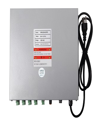
Digital to Synchro Gyro Converter ( D/A-14 ) can convert digital signals into synchronous signals. The input gyro compass signal is in NMEA0183 format, Baud rate: 4800 or 9600; Multiple statements can be identified: $--HDT、$--HDM、$--HDG, the output gyro compass signal is 110V sine wave synchronous analog signal ( R1、R2、S1、S2、S3 ). Exciting voltage 110VAC, ratio (360 : 1、180 : 1、90 : 1、45 : 1), tracking rate (8).


The ratio of compass converter is 360:1. If you need to adjust the ratio, you need to open the machine panel and set it by adjusting the dial switch on the PCB board
Baud rate setting | |||
1 | 2 | baud rate | |
ON | ON | 4800 | |
OFF | ON | 9600 | |
ON | OFF | 19200 | |
OFF | OFF | 38400 | |
Ratio setting | |||
3 | 4 | ratio | |
ON | ON | 360 :1 | |
OFF | ON | 180 :1 | |
ON | OFF | 90 :1 | |
OFF | OFF | 45 :1 | |
1. Size: 295 wide X 245 deep X 120 high mm;
2. Power supply: 220VAC or 110VAC (24VDC can be selected);
3. Exciting Voltage: 110VAC; Phase Voltage (0-50VAC)
4. Tracking speed 1-8: In order to adapt to different compass dividers (compass repeaters), the device can adjust the tracking speed, which can be divided into 8 gears; 1 gears are slow and 8 gears are fast, and the adjustment benchmark is that the dividing compass is not out of step.
5. Working temperature: -20-+70 degrees;
6. Humidity: Relative humidity: < 95%;
7. On-load: It can directly drive 1-2 azimuth compasses and 1-4 compass converters.yro converter 1-4.


 中文
中文 English